
IT cabling for Power over Ethernet
The simultaneous supply of information technology terminals with data and power via balanced copper cabling is becoming increasingly widespread.
The international standardization of "Power over Ethernet" (PoE) has helped the dual use of copper cabling for the transport of data and power to achieve a breakthrough.
The advantages of this technology are obvious. With PoE, the power supply can be controlled centrally and combined with the services for data transmission. The need for an additional low voltage supply is eliminated.
Whereas 4-pair data cabling used to be able to supply IT terminals with up to 72 W (4PPoE), single-pair data cabling is now finding its way into the supply landscape of IT objects. The "Single Pair Power over Ethernet" (SPoE) technology takes into account the energy requirements of the "Internet of Things".
This brochure provides assistance for the design and planning of information technology cabling that uses equipment for remote power supply, for example with PoE.

Advantages and benefits
Power over Ethernet has numerous advantages from which IT operators can derive usable benefits. The most important advocates are listed below:
The most important advocates:
- Saving (material and installation costs) of the 230V power supply (cable and socket)
- Comprehensive management and monitoring options (SNMP)
- Reducing energy costs by routing energy according to demand and switching off unused ports
- Fail-safe through the use of central uninterruptible power supplies (UPS)
- Worldwide assured compatibility through international standardisation
- Personal protection thanks to the use of extra-low voltages and direct current
Functionality
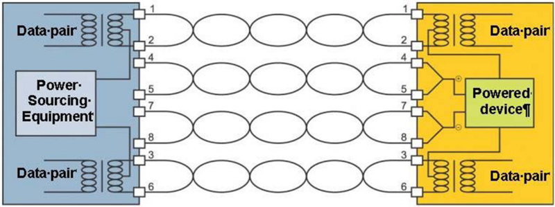
The functional principle of PoE is based on the transmission of power between the energy supplier (PSE, Power Source Equipment) and the consumer (PD, Powered Device).
The energy is supplied either via the unused data pairs or as a signal overlay via the used data pairs (phantom circuit).
PSEs are divided into "endspans" (Ethernet switches with PoE function), which are characterised by low space requirements and simple management, and "midspans" (PoE injector between switch and end device), which allow flexible or demand-oriented retrofitting.
Schematic diagram for PoE transmission
(source: IEEE 802.3)
When an end device is connected, a start-up sequence ensures that PoE-capable devices are detected so that unsuitable devices are protected.
In this case, the energy supplier initially applies only a minimal current to the wires, which normally cannot damage any device. In doing so, it detects whether the energy consumer is PoE-capable and is only then assigned the permissible power.
PoE standards in comparison
4-pair balanced cabling
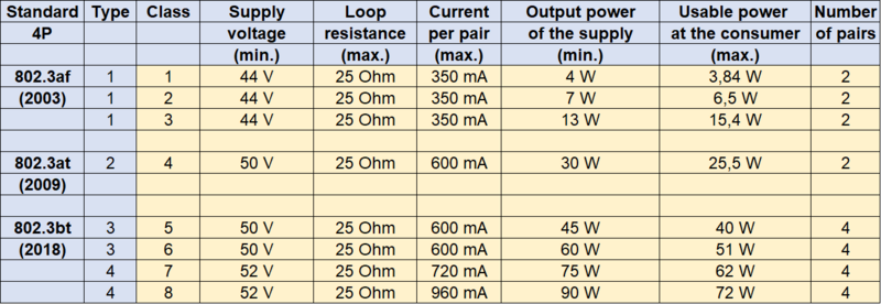
The first PoE standard appeared in 2003 with IEEE 802.3af. This made it possible for the first time to supply IT devices with power and data simultaneously via information technology cabling. Since then, the available services have been steadily increased as part of the technological development for IT equipment. The current state of the art offers IEEE 802.3bt (2018) with a usable power of 72 W!
The technical model of PoE transmission is based on the specification of a max. loop resistance of 25 ohms for the channel. This value is taken from the specification for the max. loop resistance of class D, E, EA, F and FA channels according to ISO/IEC 11801 and EN 50173. The max. loop resistance of 25 Ohm/100m is approximated from an AWG 24/1 copper conductor (0.51 mm). If larger copper conductor diameters are used, the channel length can be increased.
Single pair balanced cabling
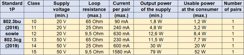
In analogy to 4-pair balanced cabling, "Single Pair Ethernet" (SPE) is also equipped with the possibility of simultaneous transmission of data and power. In IEEE 802.3bu (2016), this is still described as “Power over Data Line” (PoDL). In the meantime, IEEE has agreed on a more consistent designation, namely “Single Pair Power over Ethernet” (SPoE). In IEEE 802.3cg (2019), a variant is specified with class 15, which can provide up to 52 W as usable power at the consumer on the basis of a max. loop resistance of 9.5 ohms. This typically requires an AWG 18/1 copper conductor (1.02 mm).
Applications
There are numerous applications for "Power over Ethernet".
The advancing digitalisation in combination with the increasing awareness of sustainability is constantly opening up new fields of application. The greatest potential is probably in the area of intelligent building management and smart lighting solutions.
The following overview shows some IT devices that are typically supplied with power via PoE:
Requirements for IT cabling, data cables and connectors
IT cabling
Equipment for remote power supply of devices using information technology cabling shall comply with DIN IEC EN 62368-3 "Safety aspects for direct current power transmission via communication cables and connections".
The problems associated with power supply via information technology cabling are:
a) with global impact:
the increase in attenuation due to the higher temperature of the installed cables, which, if not compensated by shortening the installed cable lengths, has a negative impact on the attenuation-to-crosstalk ratio of the transmission link and can thus lead to a higher bit error rate of the system;
b) with local impact:
higher operating temperature of the cables, especially if the permitted continuous operating temperature is exceeded;
damage to the contacts of the connectors, due to making and breaking the connection when the supply current is flowing.
In conjunction with EN TR 50174-99-1 and ISO/IEC TS 29125, EN 50174-2 and ISO/IEC 14763-2 provide guidance on the design and assessment of the cabling, the cables and connectors in relation to the effects of thermal and electrical effects due to remote powering.
Data cable
If a communication cable system in accordance with the standards of the DIN EN 50173 or ISO/IEC 11801 series is used to supply power to the terminal devices connected via remote power supply (e.g. Power over Ethernet), the associated heating of the data cables must be taken into account.
The heating of the data cables depends on the following factors:
Power load
Cable construction
Quantity of cable bundles
Installation conditions
Since the European and international data cable standards stipulate a permanent operating temperature of max. 60°C, an ambient temperature of max. 50°C has been agreed upon in the case of a power supply via data cable, thus allowing a temperature increase of max. 10°C.
A reduction in data cable heating is achieved:
by using data cables with a larger conductor cross-section, this is usually achieved by using higher categories. Category 7A data cables typically have a 50% lower temperature rise compared to category 5 data cables.
by using additional shielded data cables. The metallic shield provides improved heat dissipation.
by reducing the number of cables in the bundle or installation channel
by improving the air circulation in the installation environment
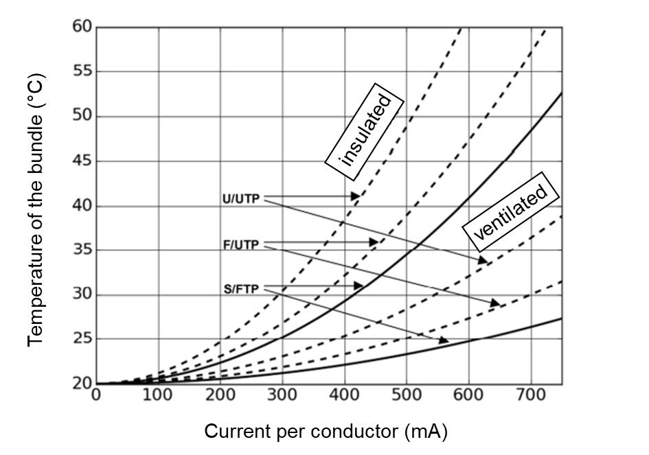
The following graph shows the approximate temperature rise of commercially available data cables as a function of the current load. The calculation was based on a bundle of 37 data cables located in an installation environment with free air circulation (ventilated) odr in an insulated installation environment (insulated). The selected S/FTP data cable has a temperature rise of <5°C with ventilated and <15°C with insulated installation at a current load of 500 mA per conductor. On the other hand, the temperature increase for the U/UTP data cable is <10°C with ventilated installation and <30°C with insulated installation.
Connectors
If the connection is disconnected under electrical load, the resulting arcing or sparks can damage the contacts. With frequent interruptions under load, this leads to the so-called contact fire. The impairments are then irreversible and can even cause the contacts to fail.
This can be remedied by port power management, which switches off the voltage or power supply before connections are disconnected or PoE end devices are disconnected from the mains. However, intentional or unintentional pulling of the plug under load cannot be reliably prevented.
For this reason, a connector technology should be used in which offset contact and separation zones exist. This does not prevent wear in the separation zone, but the operating contact remains intact.
During qualification according to IEC 60512-99-001 or IEC 60512-99-002, the connectors are subjected to a limited number of mating cycles under load. The deviation of the contact resistance must not exceed the specified value.
Product range and recommendations ZVK
For IT cabling with remote power supply or Power over Ethernet, ZVK recommends its use:
- of copper data cables with a conductor cross-section of AWG 22/1 (0.64 mm), for example the EasyLan® data cable Gold S/FTP, AWG22/1, Cat. 7A.
Data cables with a larger conductor cross-section have a lower DC resistance and lower attenuation. Thus, on the one hand, they have less heating or power loss and, on the other hand, a lower voltage drop or a longer transmission distance.
- of connectors with offset contact and separation zones, for example EasyLan fixLink® RJ45 Keystone Cat.6A.

If required and on request, ZVK can advise on the planning and installation of IT cabling with PoE function.
ZVK determines the heating of the data cables depending on the data cable construction, the number of data cables in the bundle, the current load and the installation conditions.
Furthermore, the potential reduction of the transmission distance is calculated as a function of the cable construction or the conductor cross-section and the temperature increase.
Calculation tool for determining the temperature rise by PoE
Excel-Download
Operating instructions for the calculation tool for determining the temperature rise by PoE
PDF-Download